Introduction
A machine can rotate a shaft, turn a gear, or spin a motor — but many real-world applications need something different: straight-line movement. A mechanism may need to push a component forward, pull it backward, lift a load, adjust a position, or move repeatedly between defined points. This is where a linear actuator becomes an important part of a motion control system.
An electric linear actuator takes controlled electrical input and converts it into mechanical movement. Although the concept sounds simple, several components work together to produce reliable and repeatable motion. The basic operating sequence can be understood as:
Understanding this sequence helps engineers, OEMs, machine builders, and equipment designers select the appropriate actuator for an application. This article explains how a linear actuator works, what happens inside the actuator, how motors and drive mechanisms create linear motion, how force and stroke affect performance, and how TorqX approaches actuator manufacturing and application-specific customization.
What Is a Linear Actuator?
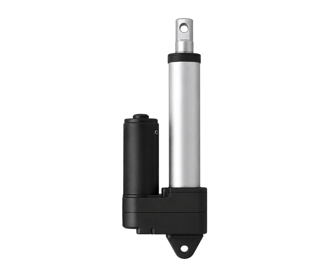
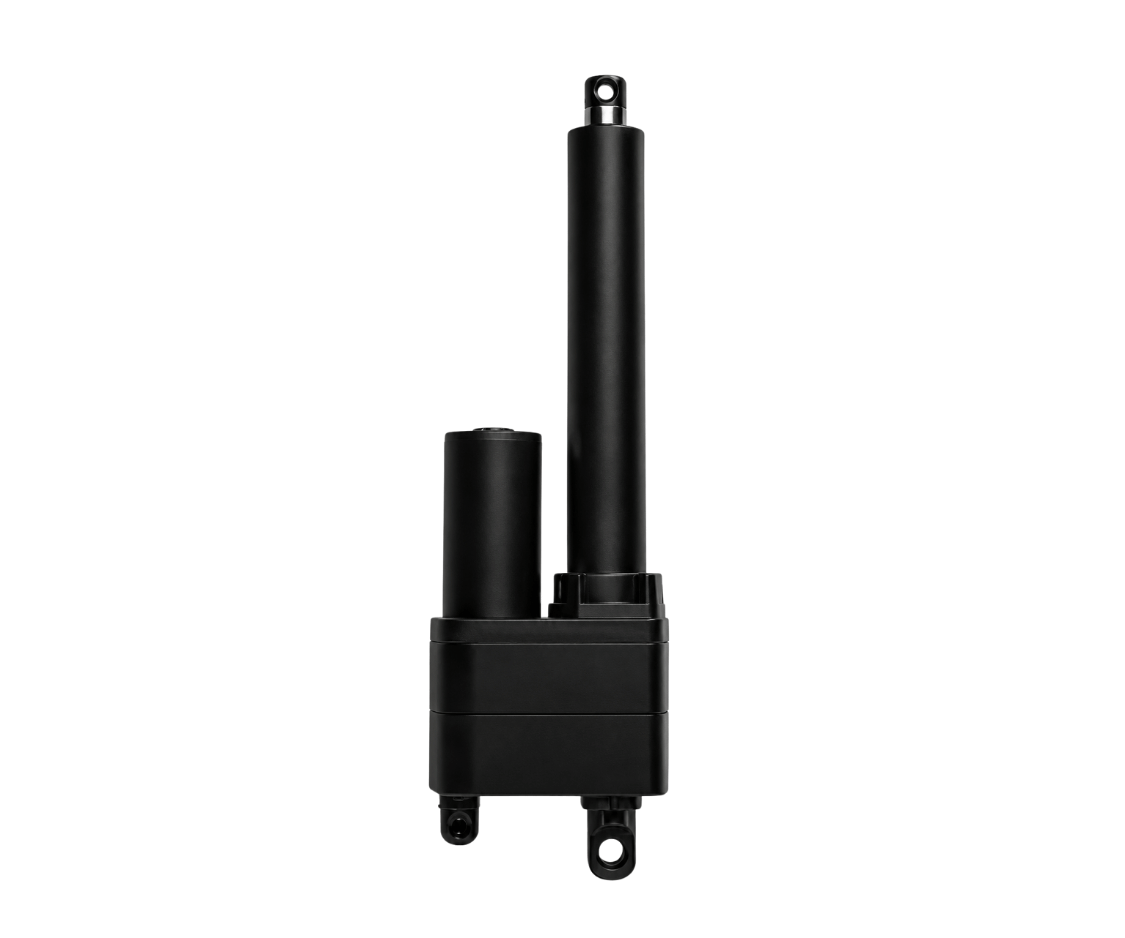
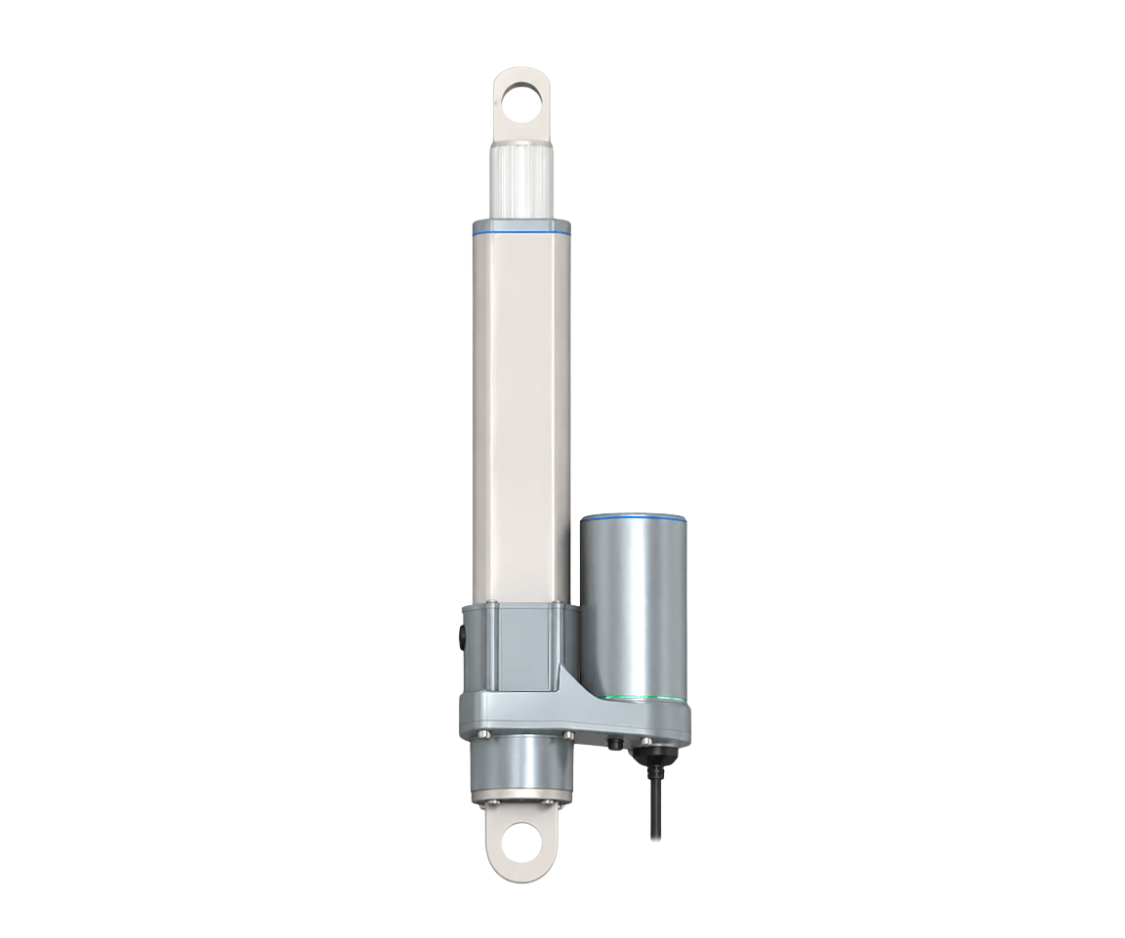
A linear actuator is a mechanical device that produces movement along a straight line. Unlike a rotary motor that primarily produces rotational movement, a linear actuator provides controlled extension and retraction. This movement can be used to create:
- Pushing motion
- Pulling motion
- Lifting motion
- Lowering motion
- Position adjustment
- Linear positioning
- Mechanical adjustment
- Automated movement
An electric linear actuator generally uses an electric motor combined with a transmission or drive mechanism to transform rotary motor movement into linear movement. A simplified system looks like this:
The exact internal architecture can vary between actuator designs. Some systems may use an ACME screw, ball screw, lead screw, or another mechanical transmission.
How Does a Linear Actuator Work?
The fundamental principle behind an electric linear actuator is the conversion of rotary motion into linear motion. The process can be divided into four major stages.
| Stage | What happens |
|---|---|
| 1. Controlled electrical input | A controller supplies electrical power and, depending on the system, a command that determines the desired direction, speed, position, or operating sequence. |
| 2. Motor generates rotary motion | The electrical energy drives the actuator’s motor. The motor rotates at a specific speed and produces torque. |
| 3. Transmission converts motor output | The motor’s rotational output passes through a mechanical transmission. A gearbox can modify the motor’s speed and torque before the drive mechanism converts the rotation into linear movement. |
| 4. Linear movement creates push/pull motion | The drive mechanism moves the actuator’s output member along a straight path, producing controlled extension or retraction. |
1. The Motor: Where the Motion Begins
The motor is the starting point of movement in many electric linear actuators. Its primary function is to convert electrical energy into rotary mechanical energy. Depending on the actuator design and application, the motor may be a DC motor, brushed motor, brushless motor, servo motor, or stepper motor. The choice of motor influences the actuator’s speed, torque, control characteristics, efficiency, and overall architecture.
DC Motors
A DC motor is commonly used where relatively straightforward electrical control is required. Changing the electrical input or polarity can allow the system to control motor operation and direction, depending on the actuator’s control architecture.
Brushless Motors
A brushless motor eliminates mechanical brushes and uses electronic commutation. This can provide advantages in applications where efficiency, operating life, speed control, and reduced mechanical wear are important.
Servo Motors
Servo-based systems are useful when precise control of movement, speed, or position is required. When combined with suitable feedback and control electronics, a servo motor can form part of a more advanced precision motion control system.
Stepper Motors
Stepper motors divide rotation into controlled steps. They can be useful for applications where controlled positioning is required, although the appropriate motor and control architecture depends on the load, speed, acceleration, and feedback requirements.
2. The Gearbox: Controlling Speed and Torque
The motor may rotate much faster than the actuator’s output mechanism should move. A gearbox or gear reduction system can therefore be used between the motor and the linear drive. Its basic purpose is to change the relationship between motor speed and available torque.
This is important because actuator applications often prioritize controlled force and movement rather than simply maximizing motor speed. For example, a machine may require a relatively slow but powerful linear movement. A gearbox can help adapt the motor’s rotational characteristics to the mechanical requirements of the actuator. The final design depends on:
- Required thrust
- Desired speed
- Motor characteristics
- Gear ratio
- Screw type
- Load
- Duty cycle
- Mechanical efficiency
This is why actuator performance cannot be evaluated by looking at the motor alone.
3. The Transmission or Drive: Converting Rotation Into Linear Motion
After the motor and any required gear reduction, the actuator needs a mechanism that converts rotational movement into straight-line movement. This is one of the most important parts of the actuator. Common drive technologies include ACME screws, ball screws, lead screws, and other mechanical transmission systems.
The principle is relatively straightforward. When a screw rotates, a corresponding nut or moving element travels along the screw’s axis. That creates linear displacement.
This is the fundamental mechanical principle behind many electric linear actuators.
ACME Screw vs. Ball Screw
The type of screw used in an actuator influences its performance characteristics.
| Screw type | How it works | Often considered for |
|---|---|---|
| ACME screw | Uses a threaded mechanical interface to convert rotation into linear movement. Screw friction can also contribute to holding characteristics when power is removed, depending on the design. | Cost, load handling, simplicity, self-locking characteristics |
| Ball screw | Uses recirculating balls between the screw and nut, reducing friction compared with conventional sliding-thread arrangements. | Higher efficiency, precise movement, smooth operation, precision positioning |
The correct choice depends on the complete application rather than assuming that one screw technology is universally better.
4. Linear Movement: Turning Rotation Into Travel
Once the screw or drive mechanism rotates, the actuator’s moving member travels along a straight path. This creates the actuator’s stroke.
What Is Stroke Length?
Stroke length is the distance the actuator’s moving element can travel between its positions. For example, an actuator with a 200 mm stroke can move its output member through a nominal 200 mm travel range, subject to the manufacturer’s specified operating conditions. Stroke selection affects installation dimensions, extended length, retracted length, available movement, mechanical design, and overall actuator size.
A long stroke actuator may be appropriate when greater travel is needed, while a shorter stroke may be preferable where installation space is limited.
5. Push and Pull Motion
The linear output of an actuator can be used to produce both pushing force and pulling force. When the actuator extends, it can push a connected mechanism. When it retracts, it can pull that mechanism. This makes a linear actuator useful for applications such as opening and closing mechanisms, adjusting machine components, positioning equipment, raising or lowering structures, moving mechanical assemblies, and controlling automated mechanisms.
The actuator itself does not determine the entire mechanical result. Mounting geometry, linkage design, load distribution, friction, and external forces all affect the actual force required.
What Is Actuator Duty Cycle?
Duty cycle describes how frequently and for how long an actuator operates within a defined period. For example, an actuator used for occasional adjustment may experience a very different operating pattern from one used repeatedly in factory automation. Duty-cycle considerations can affect motor heating, mechanical wear, thermal performance, expected service life, suitable operating speed, and actuator selection.
An industrial application should therefore specify not only what movement is required, but also how often that movement occurs.
How Control Input Determines Actuator Movement
A linear actuator becomes particularly useful when it is integrated into a broader motion control system. The control system can determine direction, start and stop, speed, position, movement sequence, and operating limits. A basic system might use a simple switch to command extension or retraction. A more advanced industrial control system may use a PLC, sensors, feedback devices, and programmed control logic.
When feedback is included, this becomes a closed loop:
This creates the foundation for closed-loop control.
Feedback and Position Control
Feedback allows the control system to understand what the actuator is doing. Depending on the design, an actuator may use:
| Feedback device | What it does |
|---|---|
| Limit switch | Can identify a predefined end position. |
| Hall effect sensor | Can provide information related to motor or actuator movement and support position or speed monitoring depending on the implementation. |
| Potentiometer | Can provide analog position feedback in suitable actuator architectures. |
| Encoder | Can provide more detailed motion information and is commonly associated with applications requiring precise position or speed monitoring. |
Feedback can be especially valuable for precision positioning, synchronization, automated machinery, repeated positioning, closed-loop control, and machine safety and control strategies. The required feedback technology depends on the application’s precision, control architecture, and actuator design.
Linear Actuator Applications
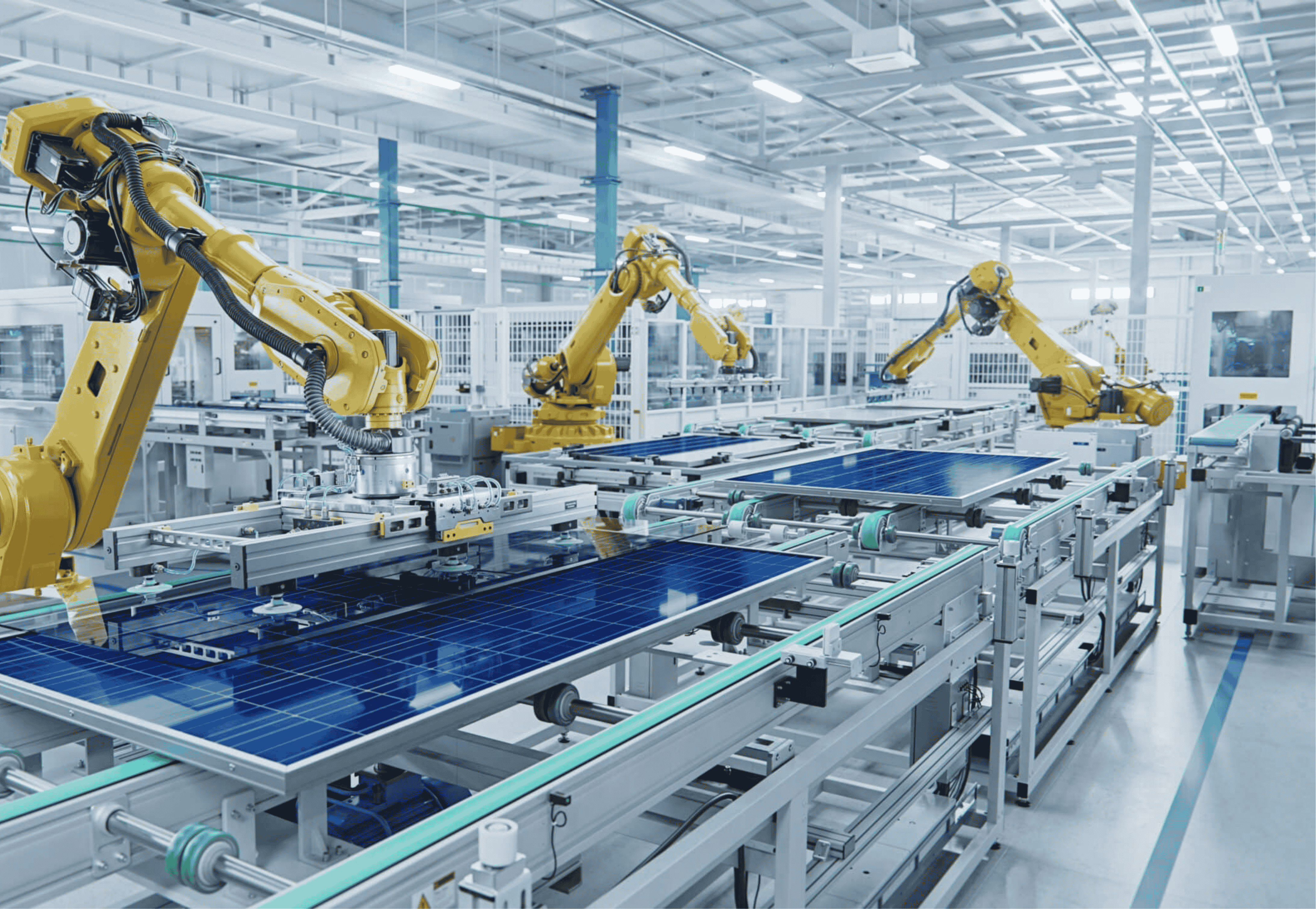
One of the most important application areas for electric linear actuators is industrial automation. Machines often need to move components in a controlled and repeatable way — for machine adjustment, automated positioning, clamping mechanisms, material handling, packaging equipment, assembly machinery, and special-purpose machines. In an automation system, the actuator becomes one part of a larger architecture involving controllers, sensors, mechanical structures, and other automation equipment.
Robotics
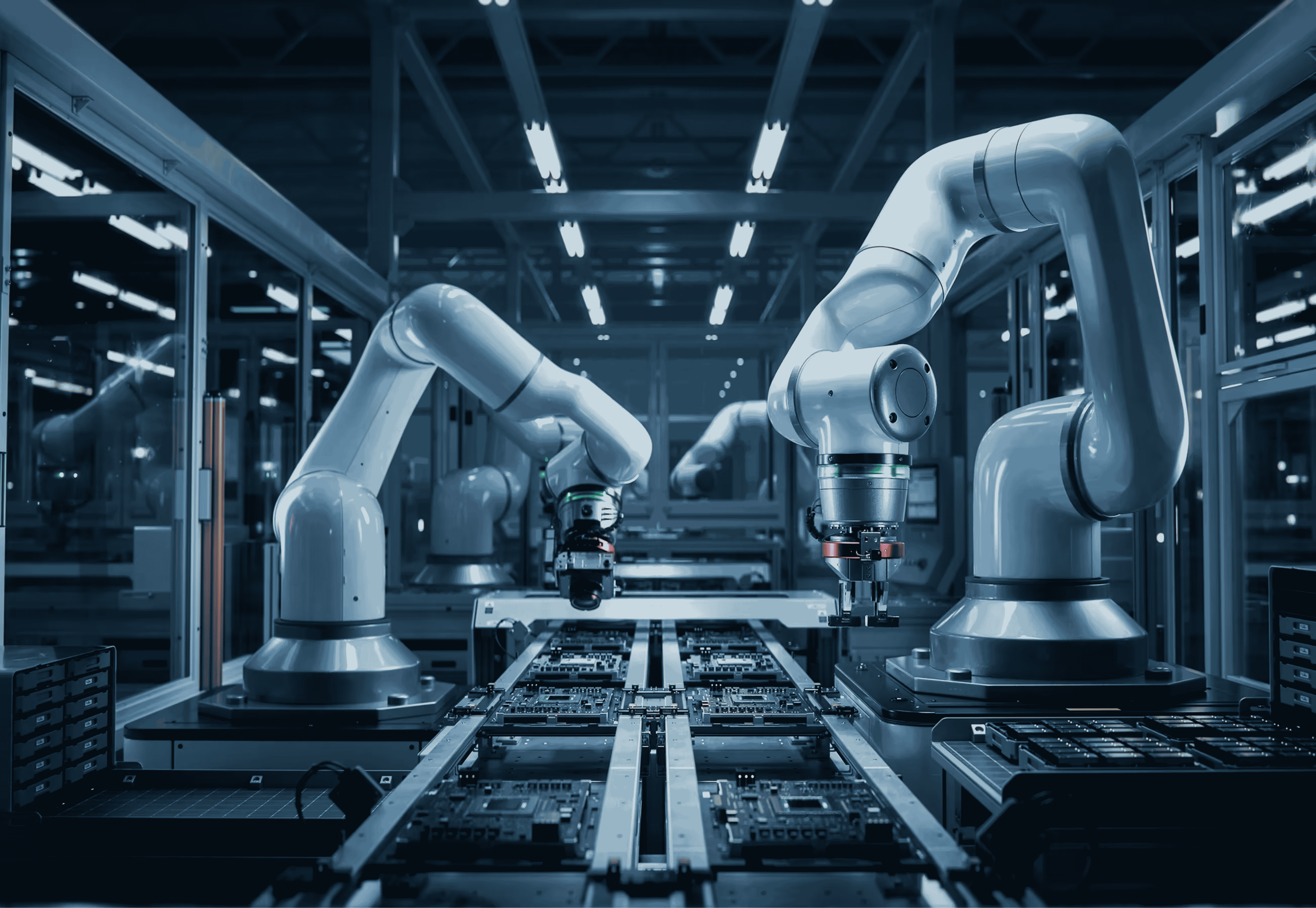
A linear actuator for robotics can provide controlled extension, retraction, positioning, or adjustment. The appropriate actuator depends on the robot’s payload, available space, movement requirements, speed, and control architecture.
Medical Equipment
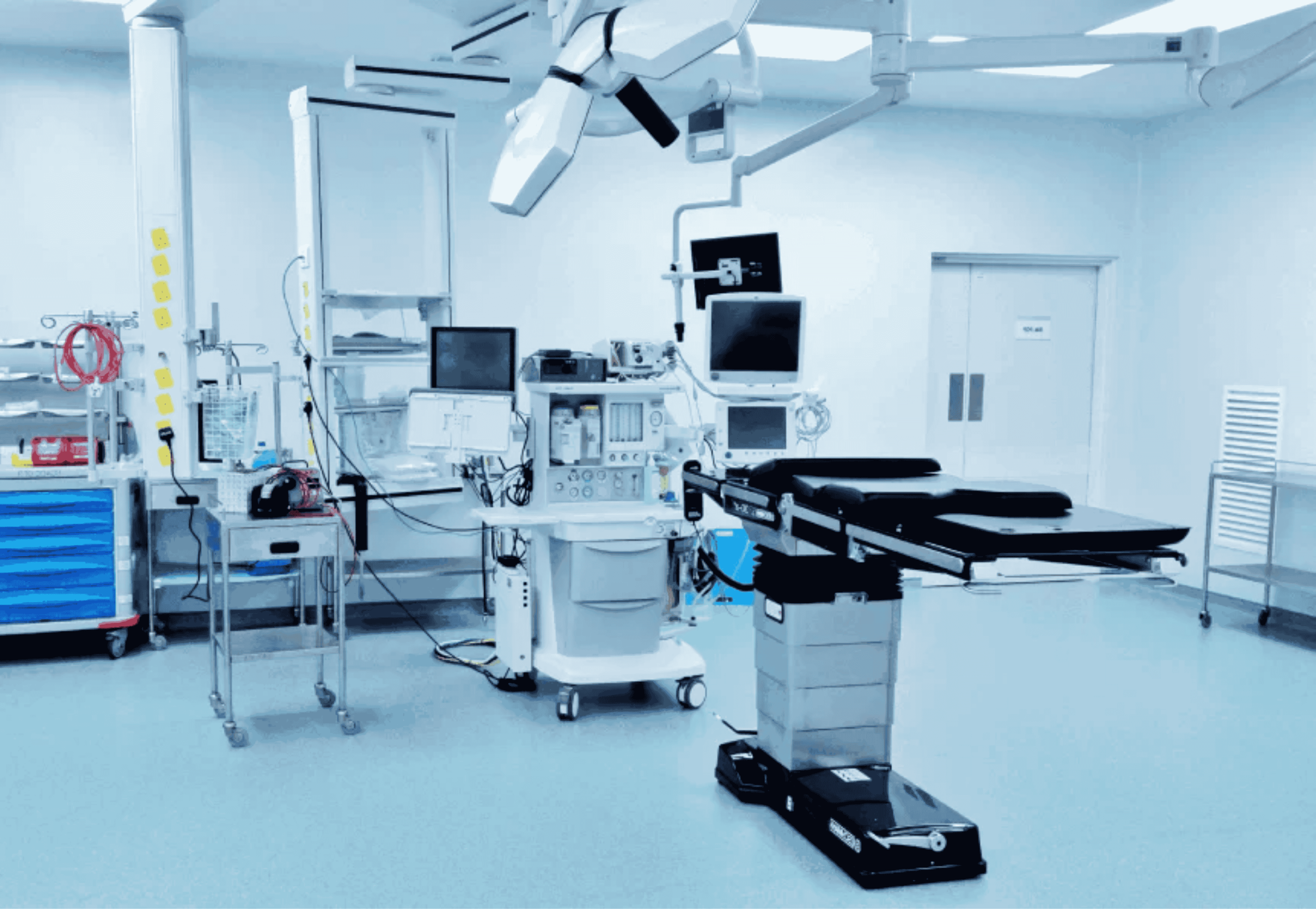
Linear actuators can support controlled adjustment in medical equipment, including hospital beds, medical tables, patient positioning equipment, and other adjustable medical systems. These applications may place particular importance on smooth movement, controlled positioning, noise, reliability, and environmental requirements.
Material Handling
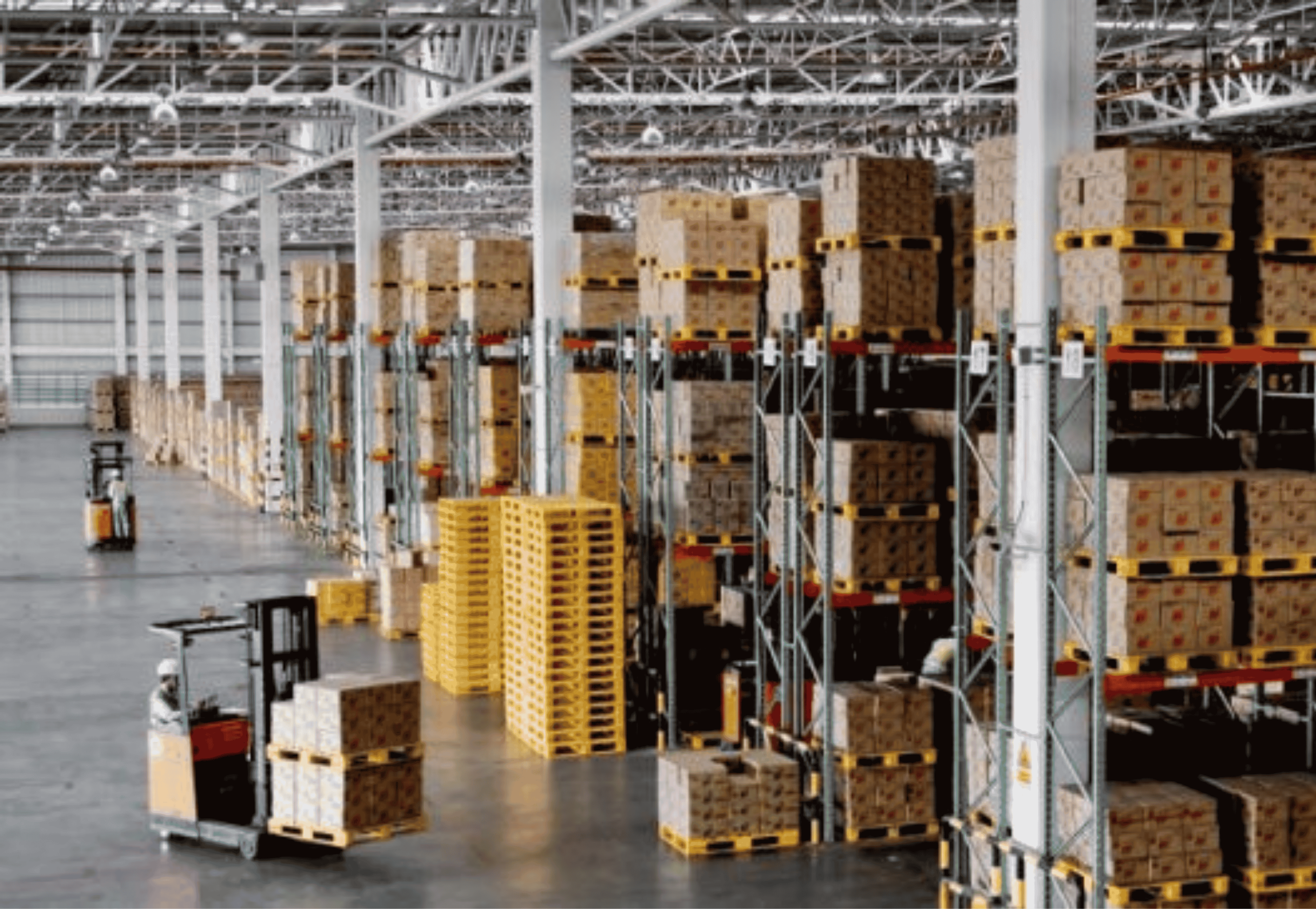
Material-handling equipment often needs controlled movement to position, lift, push, or adjust components. A linear actuator can provide this movement when its force, stroke, speed, and duty cycle match the machine requirements.
Solar Tracking

A linear actuator for solar tracking systems can adjust the position of solar equipment to support tracking mechanisms. Outdoor applications require careful consideration of environmental exposure, sealing, load, stroke, and duty cycle.
Agricultural Machinery
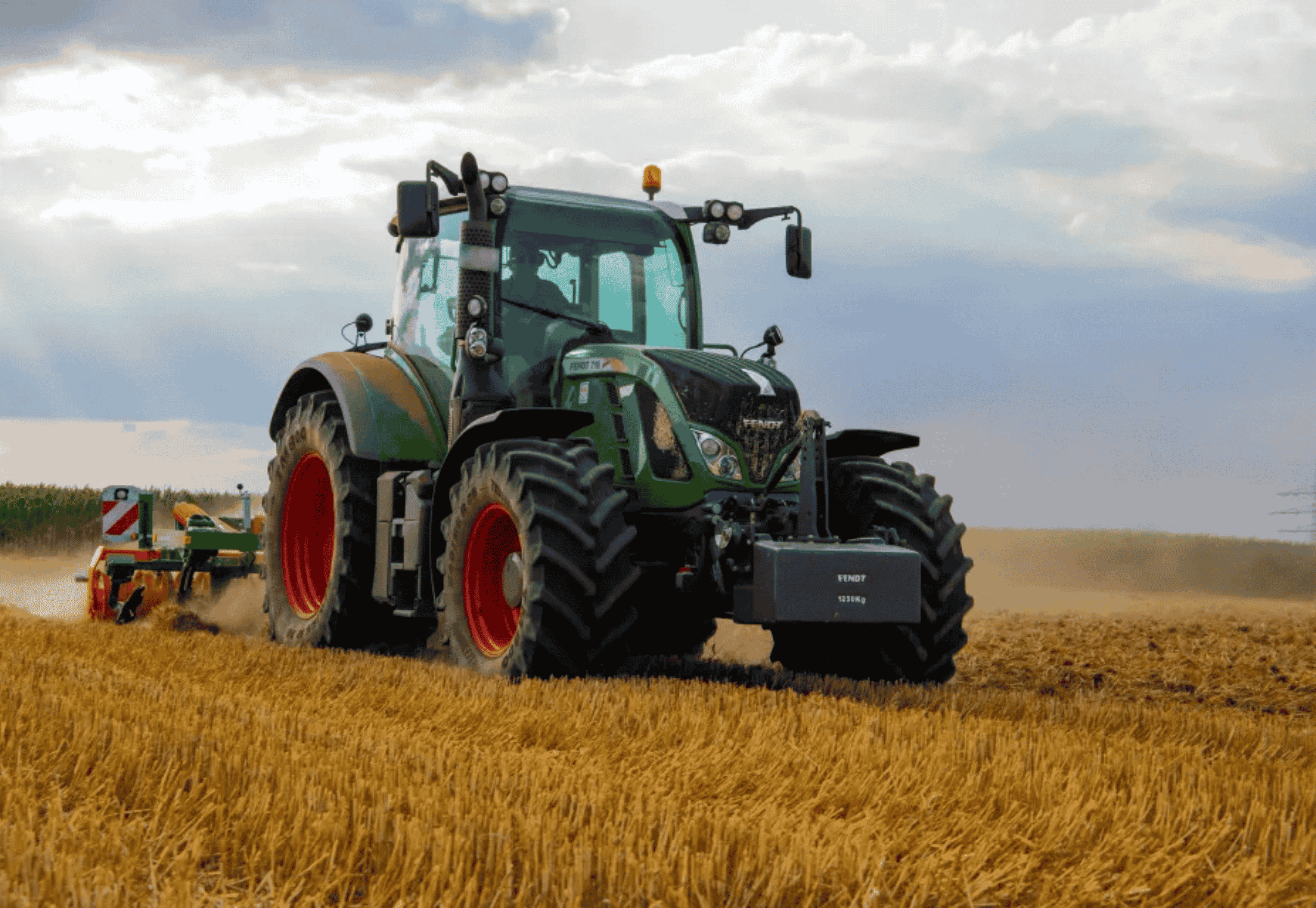
Agricultural equipment can use linear actuators for adjustment and positioning functions. Depending on the environment, protection against dust, water, and other operating conditions may be important.
Environmental Protection
Not every actuator operates in a clean indoor environment. Industrial and outdoor applications may expose actuators to dust, water, humidity, cleaning processes, temperature variation, and corrosive environments. This is where environmental protection becomes an important selection criterion.
Terms such as waterproof actuator, dustproof actuator, and IP ratings are often used when evaluating protection against environmental ingress. Depending on the application, designers may encounter ratings such as IP54, IP65, IP66, IP67, and IP69. The required rating should be selected based on the actual environmental conditions and applicable product specifications rather than assuming that a higher IP rating is always necessary.
How to Choose an Electric Linear Actuator
Selecting a linear actuator should begin with the application’s actual mechanical requirements.
- Define the movement — push, pull, lift, lower, extend, retract, or positioning.
- Calculate required force — the actual force required under operating conditions, including mechanical geometry, load, friction, acceleration, and external forces.
- Determine stroke — the required travel distance and available installation space.
- Determine speed — how quickly the actuator needs to complete the movement.
- Determine duty cycle — how frequently and for how long the actuator operates.
- Define the environment — water, dust, outdoor conditions, temperature extremes, cleaning, or corrosive environments.
- Define control requirements — limit switches, Hall sensors, potentiometer, encoder, PLC control, position feedback, closed-loop control, or CAN bus.
- Consider mechanical integration — mounting points, retracted length, extended length, load direction, alignment, available space, and required attachment points.
Only after these factors are defined should the final actuator configuration be selected.
Standard vs. Custom Linear Actuator Solutions — and TorqX
Not every machine can be designed around a standard actuator. OEM equipment may have unique requirements involving dimensions, mounting, force, stroke, speed, feedback, voltage, or environmental conditions. A custom linear actuator can be considered when a standard configuration does not adequately match the application, with customization areas including stroke length, force or thrust, speed, voltage, mounting configuration, physical dimensions, feedback, limit switches, duty cycle, environmental protection, and mechanical interface. Customization should always be based on engineering feasibility and the application’s actual requirements.
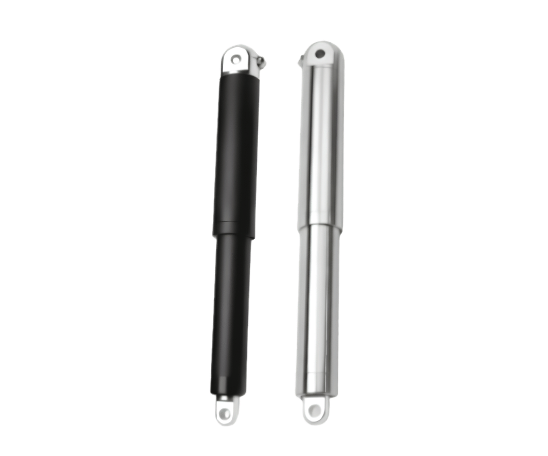
TorqX approaches actuator development from a manufacturing and application perspective. As a linear actuator manufacturer, TorqX develops actuator solutions for applications where controlled linear movement, force, positioning, and mechanical integration are important. The broader TorqX portfolio — the Comfort, Industrial, Solar, and Axis Series — can be evaluated around factors such as force, stroke, speed, duty cycle, mounting, feedback, environmental protection, and control requirements.
TorqX can work from customer specifications to customize actuator solutions where technically and commercially feasible. Engineering discussions typically follow this sequence:
This approach can be useful for OEM manufacturing, industrial machinery, automation equipment, medical equipment, material handling, and other specialized systems. The objective is not simply to provide a generic actuator, but to evaluate the actuator around the requirements of the machine in which it will operate.
Frequently Asked Questions
What is a linear actuator?
A linear actuator is a device that converts available energy into controlled straight-line movement. An electric linear actuator commonly uses a motor and mechanical transmission to produce extension and retraction.
How does a linear actuator work?
An electric linear actuator typically follows this sequence: Electrical Input → Motor → Gearbox/Transmission → Screw/Drive → Linear Movement. The resulting extension or retraction creates controlled push or pull motion.
How do electric actuators work?
Electric actuators use electrical energy to operate a motor, which produces rotary movement. A mechanical transmission converts that rotary movement into the required linear or mechanical output.
How does a linear actuator create push and pull motion?
The actuator’s output member extends and retracts along a straight path. Extension can produce pushing movement, while retraction can produce pulling movement, depending on how the actuator is mounted.
What is the difference between an ACME screw and a ball screw?
An ACME screw uses sliding contact between threaded surfaces, while a ball screw uses recirculating balls between the screw and nut. Ball screws can provide higher mechanical efficiency and precise movement, while ACME screw systems can offer advantages in simplicity and holding characteristics depending on the design.
How much force can a linear actuator generate?
The force depends on the motor, transmission, screw or drive mechanism, actuator architecture, and operating conditions. Required force should be determined from the application’s actual load and mechanical geometry.
What is actuator duty cycle?
Duty cycle describes how frequently and for how long an actuator operates. It is an important consideration because repeated operation can affect thermal performance, wear, and expected service life.
How do I choose a linear actuator?
Start by defining the required force, stroke, speed, duty cycle, mounting arrangement, environment, feedback, voltage, and control requirements. These specifications should be evaluated together.
What is a self-locking linear actuator?
A self-locking actuator is designed so that the mechanical drive can resist movement under specified load conditions when power is removed. Whether an actuator is self-locking depends on its mechanical design and operating conditions.
Can a linear actuator be customized?
Yes. Depending on the manufacturer and engineering feasibility, linear actuators can be customized around requirements such as stroke, force, speed, mounting, voltage, feedback, dimensions, and environmental conditions.
Conclusion
A linear actuator is more than a motor attached to a moving rod. It is a coordinated mechanical system in which controlled electrical input drives a motor, the motor’s rotary output passes through a transmission or gearbox, and a screw or other drive mechanism converts that rotation into linear movement.
From there, actuator performance depends on factors such as thrust force, stroke length, speed, duty cycle, feedback, environmental protection, and control requirements. This makes linear actuators valuable across industrial automation, robotics, medical equipment, material handling, agriculture, solar tracking, and specialized machinery.
For OEMs and equipment manufacturers, selecting the right actuator begins with understanding the complete application rather than focusing on a single specification. As a linear actuator manufacturer, TorqX can evaluate customer requirements and provide or customize actuator solutions where technically and commercially feasible — connecting actuator design with the application’s force, movement, control, environmental, and mechanical requirements.